 Formada3D
 Design for FDM: tolerances, walls, holes and fits
A 3D-printed part is not a machined part, and drawings that treat it like one are the commonest reason a first print does not fit. Here is what to expect from FDM in the real world and the handful of design rules that make parts print and assemble first time.
The short answer
- Tolerance: plan on about ±0.2–0.3 mm on most features, and holes that print slightly small.
- Walls: at least three extrusion lines (about 1.2–1.6 mm) for anything functional.
- Fits: design loose or sliding fits at about 0.2 mm per side and test before printing a large run.
- Overhangs: keep surfaces steeper than about 45° from vertical, or accept supports.
- Orientation: layers are the weak direction. Tell us where the load goes.
What tolerance does FDM really give?
FDM builds a part by laying down melted plastic in lines about half a millimetre wide, one layer at a time. Plastic shrinks as it cools, corners round off slightly and the first layers squash a little against the build plate. The result is a part that is dimensionally good but not precise in the way a CNC part is. For every FDM material we print, we quote About ±0.2–0.3 mm on most features. Holes print slightly small; tell us the fit you need.
It helps to compare that with a tolerance standard you may already use. ISO 2768-1 sets general tolerances for linear dimensions that apply when a drawing gives none. Its “medium” class allows ±0.2 mm for features from 6 to 30 mm, ±0.3 mm from 30 to 120 mm and ±0.5 mm from 120 to 400 mm. FDM sits close to that for mid-sized features. It does not reach ISO 2768 “fine” (±0.1 mm for 6–30 mm) as a general rule, and it should not be asked to.
| Feature size | ISO 2768-1 fine | ISO 2768-1 medium | What we quote for FDM |
|---|---|---|---|
| 6 to 30 mm | ±0.1 mm | ±0.2 mm | About ±0.2–0.3 mm |
| Over 30 to 120 mm | ±0.15 mm | ±0.3 mm | About ±0.2–0.3 mm |
| Over 120 to 400 mm | ±0.2 mm | ±0.5 mm | Discuss: large parts can warp or shrink more |
Sources: ISO 2768-1:1989 table 1, general tolerances for linear dimensions (see ISO 2768-1); FDM figure from our materials guide, data version 2026-10-11.3. The FDM column is our workshop quote, not a standard, and is not a guarantee for every part.
Two practical points. First, tolerance is not one number for a whole part: the top face, the sides and the hole through the middle each behave differently, because they are made by different moves of the printer. Second, the tolerance that matters is the one at the mating feature. If only two surfaces must meet, tell us which, and we will print and check those with care rather than treating every dimension equally.
The design rules that matter most
These are our workshop rules of thumb from printing brackets, housings and fixtures for robotics and sensor projects. The same ideas appear in published FDM design guides such as Hubs' guide to designing parts for FDM and the UNSW Making FDM tutorials; limits vary between printers, nozzles and materials, so treat the numbers as a starting point.
| Feature | Our rule of thumb | Why |
|---|---|---|
| Walls | At least 3 lines, about 1.2–1.6 mm. Use multiples of the line width. | A wall that is not a whole number of lines gets a gap or an odd fill. One-line walls are fragile. |
| Holes | Add about 0.2 mm to the diameter for a screw or pin to pass; ream or drill if it must be exact. | Holes print slightly small because the nozzle path sits inside the circle. |
| Sliding or loose fits | About 0.2 mm per side; test 0.15 to 0.30 mm. | Outer faces print oversize and slots undersize, so a CAD gap of 0.05 mm jams. |
| Press fits | Test a coupon first; start tight and open up. | Material, layer height and part size all change the result. |
| Overhangs | Keep to about 45° from vertical; use chamfers instead of flat undersides. | Steeper overhangs sag or need support. |
| Bridges | Keep unsupported spans short, a few centimetres at most. | Long spans droop in the middle. |
| Corners | Add fillets or chamfers at stress points and at the bottom edge. | Sharp internal corners concentrate stress; the first layer can flare at the base. |
| Small text and detail | Raise or deboss by at least 0.6 mm and keep strokes at least a line wide. | Finer than the nozzle will not resolve. |
Getting fits right
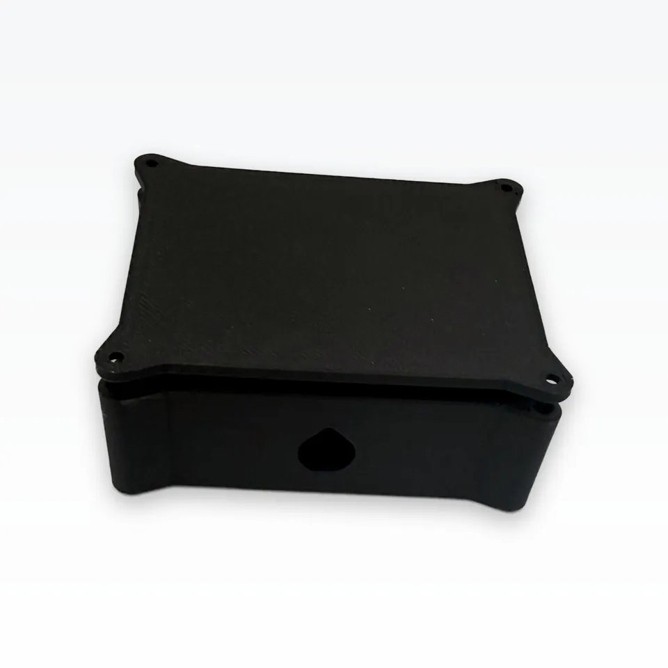
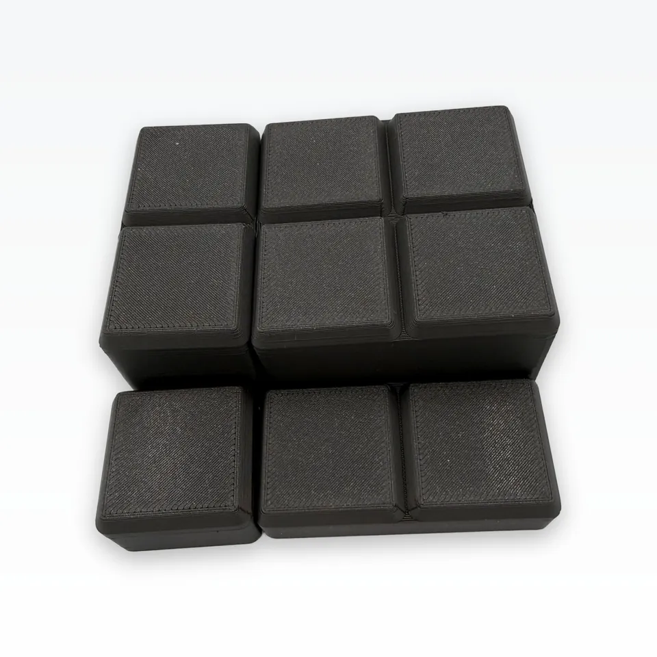
Fits are where most first prints go wrong. Printed outer surfaces come out slightly oversize and inner slots slightly small, so a gap that is zero or tiny in CAD becomes an interference in plastic. We have learned this the hard way: sliding parts designed at 0.05 mm per side would not go together at all in our workshop, and around 0.2 mm per side is where they start to move freely.
- Choose which part is the variable one. If a fit is uncertain, make the small, cheap piece (the key, spline or pin) the one you can reprint, and keep the big part fixed.
- Print a test set. A few small coupons at 0.15, 0.20, 0.25 and 0.30 mm per side take little time and save a failed large print. Mark them so they cannot be mixed up.
- Do not trust one coupon for a big part. Large parts warp and shrink differently, and several studs or pins engaging at once over-constrain the fit. We pick one step looser than the coupon's snug winner for multi-stud joints.
- Use hardware where precision matters. A press-in threaded insert, a reamed hole or a dowel gives a better, repeatable result than a printed thread or tight printed bore. Add a clearance pocket for the insert and tell us what size it is.
If a fit is critical, say so when you quote. We can print the mating features first as a test and adjust before the rest.
Orientation and strength
An FDM part is strongest along its layers and weakest between them. A tall, thin hook printed standing up can snap cleanly along a layer line under a load that a flat-printed hook would shrug off. Orientation also decides which faces carry support marks, which are smooth, and where holes come out round. A few habits help:
- Point loads along layers, not across them, where you can.
- Put your best-looking or mating face on the build plate side or on top, and keep supports off it.
- Split awkward shapes into two parts that each print flat, then bolt or glue them together.
- Raise wall count before raising infill; extra perimeters add more strength per gram than denser infill in most brackets.
Material changes things too. Our PLA vs PETG vs ASA guide covers heat and sun, and the materials guide lists all 25 materials with datasheet links.
What to send us
- A STEP file if the part has to fit something, or STL, 3MF or OBJ for shapes.
- Which dimensions are critical, and what they mate with.
- Where the part lives (indoors, outdoors, heat) and what load it carries.
- How many you need. Bulk tiers and lead times show in the instant quote.
Not sure your design will print? Send it anyway. We check wall thickness, overhangs and hole sizes before printing and tell you if something should change.
Values and suitable use
Typical datasheet values for the raw material, not guaranteed properties of a printed part. Our parts are prototypes and general-purpose parts: not designed or tested for aircraft, vehicle safety systems, medical devices, life support, lifting or load-bearing safety equipment, pressure vessels, weapons, or any use where failure could injure or kill someone. Test a sample for your use. This doesn’t affect your rights under the Australian Consumer Law. Design numbers in this guide are rules of thumb, not guarantees. Full wording: terms, suitability.
Sources
- ISO 2768-1:1989, General tolerances, tolerances for linear and angular dimensions without individual tolerance indications (the general tolerance classes in the table above).
- Hubs, How to design parts for FDM 3D printing (published design guidance).
- UNSW Making, 3D printing: FDM tutorials.
- Our materials guide (data version 2026-10-11.3), the source of the FDM tolerance wording; fit clearances are from our own workshop test prints.
Common questions
What tolerance can I expect from FDM 3D printing?
On most features we quote about ±0.2–0.3 mm, and holes print slightly small. That is looser than machined metal and roughly in line with ISO 2768-1 “medium” for features of 6–120 mm. Small, thin or very long features can drift further, so tell us which dimensions matter.
How much clearance do I need for parts that slide or press together?
As a starting point, design sliding or loose fits at about 0.2 mm per side, and run a small test set at 0.15, 0.20, 0.25 and 0.30 mm before committing a large part. A design gap of 0.05 mm per side, which looks fine in CAD, usually will not assemble at all. For a part with several studs or pins at once, choose one step looser than a small test coupon suggests.
What is the thinnest wall I should design?
Make walls a whole multiple of the extrusion line width (about 0.4–0.6 mm depending on nozzle) and for functional parts go to at least three lines, roughly 1.2–1.6 mm. Thinner walls print but are fragile. If your CAD has a 0.8 mm wall, tell us and we will check it before printing.
Do I need supports?
Surfaces steeper than about 45° from vertical usually print without them; flatter overhangs and unsupported bridges need support or a redesign. Supports leave marks where they touch, so orient the part so that surface is not a mating or visible face, or split it into two parts.
Are 3D-printed parts equally strong in every direction?
No. FDM parts are built in layers and are weakest between layers, so a load that pulls layers apart (a tall thin hook printed upright) fails far sooner than one that runs along the layers. Choose the print orientation with the load in mind and tell us how the part is used.
Which file should I send?
STEP is best for a part that has to fit something, because we can measure and adjust it. STL and 3MF are fine for shapes. Upload to the instant quote, or send drawings and sketches through the enquiry form.
Have a design? Check it and price it.
Upload STEP, STL, 3MF or OBJ for an instant price. Tell us the critical fits and we will check them before printing.
Published 13 October 2026.